My First 2D Game in UE4: Moving Platforms and Blueprints
 |
| Moving Platforms |
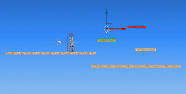
This tutorial is the second part of the Platforms tutorial. Here we will create Blueprints for our moving platforms. Having the platforms as Blueprints will allow us to give these platforms instructions of how to behave. To do this we will have to give our first steps in the Event Graph and the Construction Script and start to create some Variables.
Creating the blueprint
We are going to start by duplicating the texture that we already have for our platforms. I like to do it this way this so I can do as many modifications to the platform as I want without affecting the fixed platforms, as having a different material applied, or diferent sizes. |
| Content Browser: Textures |
Travel to your Texture Folder in the Content Browser, right-click on the texture and select from the menu Duplicate and Rename the texture conveniently so you can identify it easily. Now from this texture create a New Sprite and drag the sprite to the Sprites Folder
Still in the content Browser find the Blueprints Folder. Right-click in an empty space and select Blueprint Class
 |
| Creating a Blueprint |
This will open a new menu where you have to select a Blueprint Class Actor
 |
| Selecting Blueprint Class |
Name your blueprint. I will name mine as MovingPlatform_BP.
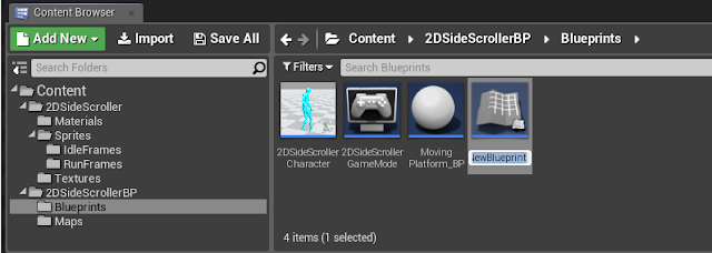 |
| Content Browser: Naming Blueprint |
Now if you double-click in your blueprint You will open all the information about the Blueprint and the Construction Script, the Event Graph, and the Viewport of the Blueprint.
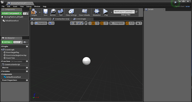 |
| Blueprint Viewport |
 |
| Add Component Panel |
| Details Panel: Adding a sprite |
Drag the Paper sprite in your Components panel in the left hand side of the screen in the DefaultSceneRoot. Now Add a new component Scene and call it Root and drag this Root on the PaperSprite
 |
| Components Hierarchy |
Above your viewport Compile and Save. You can minimize your blueprint window for now.
You can drag now the blueprint in your scene and will behave like a normal sprite. In order to have the platform moving in our game we have to do some programming in the Construction Script and the Event Graph.
To understand the difference between them think of a car. The fact that the car has an engine and wheels does not imply that the car is moving in the road, you need to start the engine with a key in order to make the car move. Well, in the Construction Script we build the car, and the Event Graph is the key that starts the engine.
Creating Variables
“Variables are properties that hold a value or reference an Object or Actor in the world. These properties can be accessible internally to the Blueprint containing them, or they can be made accessible externally so that their values can be modified by designers working with instances of the Blueprint placed in a level” (Unreal Engine, 2019)Check Unreal documentation here to have a better understanding of what the variables are.
We are going to create the following variables for our lift.
 |
| Variables |
 |
| Creating a Variable |
Create a new variable and call it EndLocation but this one is going to be a Vector, and to change this again, click in the little tab to the left of the name and unfold the menu, and from there chose thee yellow option Vector. Create another 2 more variables of green colour (Float) for your StopDelay and for TravelTimeSeconds. Finally create one to change the colour of our platform if we want and call it LiftColor. This last one is going to be a linear colour class of variable which is not available straight away in the menu, to find it type in the search bar colour and choose the category. Make sure all 5 variables are public clicking in the little eye so we can access them later.
Click in the EndLocation variable to open its Details Panel in the right side of the screen and activate Show 3D widget and set the default value Z to 100 to be able to see in the viewport the difference between initial location and Endlocation.
To the TravelTimeSeconds Variable also give a value greater than 0.
In the variable Details Panel Change the Category from Default to LiftControls typing this new category. You can do this for all of the variables individually or you can go back to the panel of your left and drag the variables inside this category.Select the color variable and in its details panel make sure it is not transparent (A value to 1)
 |
| Variable Details Panel |
The Construction Script
Make sure you are in the Construction Script tab.
On an empty space of your construction Script right click to open the menu and type Set Relative Location. From the options chose the one for the sprite. Connect this to the Construction Script node that is already on the screen.
 |
| Set Relative Location |
Drag to your graph the variables End Location, TestEnd Location, and LiftColour. When you drag the on the graph you are given 2 options, Set or Get. Chose Get. Another way to Get the variable is dragging + Ctrol.
 |
| Dragging Variables to the Graph |
From the Endlocation variable in the graph drag the node and type Select Vector and connect also the TestEndLocation variable to the pick A node
 |
| Select Vector |
Now connect the Return Value of the Select Vector to the New Location node in the SetRelativeLocation.
 |
| Conecting to the New Location Node |
Your graph should look like this.
To set the colour pull from the location exec node (the triangular that is not connected yet) and type SetSpriteColour. Connect the LiftColour variable to the New Colour Node. In the Details Panel to your right, make sure the A value (alpha: Transparency) is set to 1.
Your Construction Script should look like this.
 |
| Set Sprite Colour |
This is all we need for this tutorial in our Construction Script
The Event Graph
Beside Tab of the construction script, you can see the tab for the Event Graph.First thing we are going to do is to call a time line for our platform. Right click in an empty space of the Event Graph viewport and type Timeline and in the bottom, you can see the option Add Time line. We can name this LiftTimeLine.
 |
| Time Line |
Double click in the timeline and we will open another screen
 |
| Inside the Time Line |
We click the icon with the F+ and a timeline will show up. We can call this Driver.
 |
| Adding Float Track |
You can zoom in and out of the track with the wheel of your mouse. Right click in the point (0,0) of the time line and add a key to CurveFloat. Find the point (1,0) and add another key.
 |
| Adding a Key to the Curve |
Finally, in the options above the timeline click “Use last Keyframe? “and “Autoplay”.
 |
| Use last keyframe and autoplay |
Compile and Save
We go back to the Event graph. We want 2 events to take place in our timeline. We want our lift to move forward and once there to move backwards. For this we are going to add 2 Custom Events and call then LiftForward and LiftBackward. To create these events just right click in a blank space of your graph viewport and type Custom Event and select Add Custom Event. Hook the first to the Play From Start node and the second to the Reverse from End as shown in the next image.
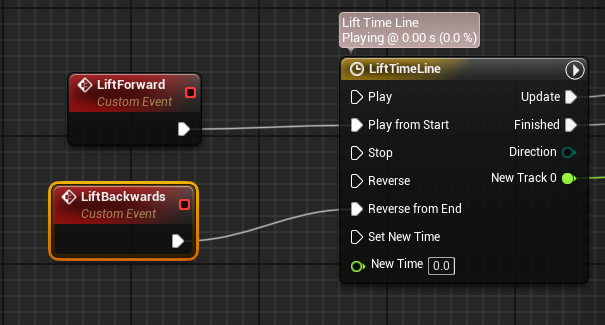 |
| Adding Custome Events |
From the driver of the timeline drag and type “lerp (vector)” and from there, from the node B we will get by dragging the node our End Location
 |
| Adding a Lerp (Vector) |
From the return value of the lerp we are going to drag a location where our left should End. We connect this SetRelativeLocation with the Update in our TimeLine
 |
| Set Relative Location |
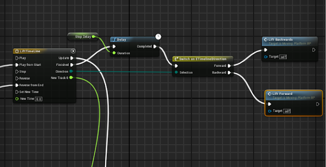
We want our lift to reverse when it reaches the EndLocation. From the Finished node in the timeline we can pull a Switch Timeline Direction and from there we are going to invert the Events from the Forward node we pull LiftBackwards and from the Backwards node we pull LiftForward. Connect the Selection node in the Switch to the Direction node in the Timeline.
 |
| Switch Time Line Direction |
To allow our character to have time enough to jump in the platform we have to indicate to the lift to have a Delay before it goes back to the initial position. We are going to put a Delay between the Update node of the Time Line and the Switch TimeLine direction node and in the Duration of the Delay we are going to connect our variable StopDelay to have option to change this when editing our game in the viewport using the details panel.
 |
| Delay |
In the Details Panel of the StopDelay Variable in the bottom we can change the default Value for the Delay to 2 seconds, but we will be able to modify this for every individual blueprint that we drag into our viewport later in the Details Panel. Compile and Save.
You can test now the platform and if you have followed all the steps it should be working, but there is still one problem to solve.
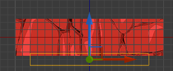
When you test your character gets trapped under the platform if they collide. We want the platform to change its direction also when it touches the character. For this we are going to create a collision box for our sprite. Add a new component Searching in the search bar for Box Collision, you can name it Collider.
 |
| Safety Collider |
In the viewport of your Blueprint scale this collider as shown in the image (remember: Switch between tools with space bar)
 |
| Blueprint Viewport |
With the Collider Selected scroll down in your details panel until you find the group of green tabs. These are used to add events to our graph events. Select On Component Begin Overlap. This should open an event in the blueprint Graph Event
 |
| Event "On component begin overlap" |
From the event we pull the 2DSideScrollerCharacter, because this event is referring to him. And connect the object node to the OtherActor node of the event.
 |
| Cast to 2DSide Scroller Character |
Now we want to stablish some condition for the left to change the direction of the time line. From the 2Dside scroller pull and type Branch. First condition is that our the timeline of our lift is active. Drag from the Blueprint Panel the LiftTimeLine to the graph.
From there we are going to pull the first condition: Is active and connected to the condition node in the branch
 |
| Branch condition and Is Active |
If this is true we want to stablish a second condition: from the true node of the branch we pull another branch and from the reference to the LiftTimeLine we type Is Reversing to connect to the condition node. We connect the True node of the branch to the Play of the TimeLine and the false node to the reverse of the TimeLine
 |
| Condition Is Reversing |
We can test now and the lift should be working perfectly.
The last bit of code that we are going to do in the graph will allow us to change the time that the lift takes to move along the distance that we specify.
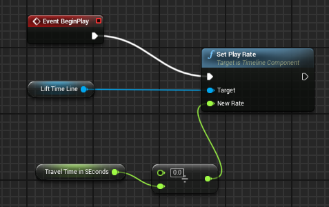
We can use the Event Begin Play. Right click and type if is not already in your Event Graph. Drag a reference to your timeline to the graph and from this reference pull the Play Rate command. Link to the Event.
Drag to the graph the Travel Time variable and from there pull Float/float and give a value of 1. Link this to the New Rate node in the Play Rate. Change the travel type from the top node to the bottom node,
 |
| Set Play Rate |
Finally from the play Rate We pull the Set End Location and click the condition Box.
With this last piece of coding we will be able to change the speed of travel of our platform in the Main construction screen and Details Panel.
Just duplicate the blueprint and add a new sprite to have different types of platforms.
This example of moving platform can be used also to build as many obstacles as your imagination can design sometimes by just adding the ability to cause damage to our character. Do you like to know how to improve further this Platforms and even make your enemies out of them? Jump to the next tutorial of these Series and learn how to do it.
My First 2D Game in UE4: Moving Platforms and Blueprints
 Reviewed by Maria Cereijo
on
March 11, 2019
Rating:
 Reviewed by Maria Cereijo
on
March 11, 2019
Rating:


